Flashing Tasmota on a Tuya based Bulb
04 Oct 2022
I've lately wanting to try out fancy bulbs controllable through my android phone so I don't have to get up to switch them off while I'm sleepy.
A big push back to me from trying out such bulbs is the lack of control. I didn't want to get too fancy and most bulbs that just do the job have a cloud server acting as middle-man between the bulb and its corresponding mobile app, which sounds really uncomfortable.
I came to know about Tasmota while looking for bulbs that work over local network and don't have to depend on a 3rd party's cloud server. Looking around for such bulbs, it seems bulbs with pre-installed Tasmota aren't as common, especially with local vendors. One of the few I stumbled upon was Athom Bulbs but these would come out to be pretty expensive considering import duties and all. Nope, won't work.
Researching a bit more, I came across tuya-convert for ESP micro-controllers. So, it seems like most bulbs which connect over the 3rd party cloud are based on Tuya but re-branded, and most Tuya based bulbs if not all use some kinda ESP micro-controller to communicate to the GPIOs and connect to WiFi. These Tuya based devices seemed to have a vulnerability in the past where you could install a custom firmware over-the-air and take it off the 3rd party cloud. This vulnerability seems to have been fixed by Tuya as of 2020 and the newer devices need to ripped apart and have to be connected via serial port through the RX/TX GPIO pins present on the micro-controller to install a custom firmware.
However, there are still re-branded Tuya devices around as 2022 that have this vulnerability. I started to look for never-heard-of-before brands on local retailer websites, since it felt like those would be based on Tuya, as well as pre-loaded with a vulnerable firmware. And it seems I did get lucky with this $5 RGB Bulb.
Installation
On receiving the bulb, the box in which the bulb came in was branded by JBT, while the one on the retailer's website mentioned ONTUBE. It wasn't problem to me since specifications seemed to match on paper. A few things I found interesting was that the mobile app's UI that the manual mentioned to install (Lumary) seemed awfully similar to Smart Life which is pretty popluar with Tuya based devices! This and along with how the bulb entered into pairing mode (ON-OFF-ON-OFF-ON) seems to be in-sync with Tuya. At this point, I was almost certain the bulb's based on Tuya.
I was careful to not feed in my WiFi's SSID anywhere on the mobile app as I've read around that Tuya devices tend to auto-update their firmware on the smell of Internet, which would be a problem if the bulb updated to a not-vulnerable firmware.
Looking more into how I can experiment with tuya-convert, it seemed like installing it on my native machine isn't a good idea as it tends to mess up with network settings to get up working. I have a Raspberry Pi Zero W around which I loaded up with fresh Raspberry Pi OS off the Internet as a means to not having to mess with my native machine.
This method had a slight problem as I use my Pi in headless mode and I won't be able
to stay connected via SSH if tuya-convert messes up with Pi's network settings. I worked around this by
setting up my Pi to be usable as an Ethernet gadget which can be done by adding dtoverlay=dwc2 to Pi's
/boot/config.txt (make sure to comment out any previous lines with dtoverlay) and appending modules-load=dwc2,g_ether
to Pi's /boot/cmdline.txt. Now connecting through the micro-USB data port on the Pi to my native machine with USB A,
and changing Ethernet network settings on my native machine to "Shared to other computers" should show a new
Ethernet interface on your native machine when the Pi boots up. If you also entered a WiFi SSID, then you can SSH
into the Pi and get the IP address our Pi got assigned on the USB gadget interface from running hostname -I.
Then you can reconnect SSH using this USB gadget interface's IP address.
Tuya-convert can now have the built-in WiFi all for itself. Following the steps to use tuya-convert:
pi@raspberrypi:~/tuya-convert $ sudo ./start_flash.sh
tuya-convert v2.4.5
Checking for network interface wlan0... Found.
Checking UDP port 53... Available.
Checking UDP port 67... Available.
Checking TCP port 80... Available.
Checking TCP port 443... Available.
Checking UDP port 6666... Available.
Checking UDP port 6667... Available.
Checking TCP port 1883... Available.
Checking TCP port 8886... Available.
======================================================
  Starting AP in a screen
  Starting web server in a screen
  Starting Mosquitto in a screen
  Starting PSK frontend in a screen
  Starting Tuya Discovery in a screen

======================================================

IMPORTANT
1. Connect any other device (a smartphone or something) to the WIFI vtrust-flash
   This step is IMPORTANT otherwise the smartconfig may not work!
2. Put your IoT device in autoconfig/smartconfig/pairing mode (LED will blink fast). This is usually done by pressing and holding the primary button of the device
   Make sure nothing else is plugged into your IoT device while attempting to flash.
3. Press ENTER to continue


======================================================
Starting smart config pairing procedure
Waiting for the device to install the intermediate firmware

IoT-device is online with ip 10.42.42.42
Stopping smart config
Fetching firmware backup
  % Total    % Received % Xferd  Average Speed   Time    Time     Time  Current
                                 Dload  Upload   Total   Spent    Left  Speed
100 1024k  100 1024k    0     0  46886      0  0:00:22  0:00:22 --:--:-- 17747
======================================================
Getting Info from IoT-device
VTRUST-FLASH 1.5
(c) VTRUST GMBH https://www.vtrust.de/35c3/
READ FLASH: http://10.42.42.42/backup
ChipID: c29fce
MAC: D8:F1:5B:C2:9F:CE
BootVersion: 7
BootMode: normal
FlashMode: 1M DOUT @ 40MHz
FlashChipId: 144051
FlashChipRealSize: 1024K
Active Userspace: user2 0x81000
======================================================
Ready to flash third party firmware!

For your convenience, the following firmware images are already included in this repository:
  Tasmota v8.1.0.2 (wifiman)
  ESPurna 1.13.5 (base)

You can also provide your own image by placing it in the /files directory
Please ensure the firmware fits the device and includes the bootloader
MAXIMUM SIZE IS 512KB

Available options:
  0) return to stock
  1) flash espurna.bin
  2) flash tasmota.bin
  q) quit; do nothing
Please select 0-2: 2
Are you sure you want to flash tasmota.bin? This is the point of no return [y/N] y
Attempting to flash tasmota.bin, this may take a few seconds...
Flashed http://10.42.42.1/files/tasmota.bin successfully in 21124ms, rebooting...
Look for a tasmota-xxxx SSID to which you can connect and configure
Be sure to configure your device for proper function!

HAVE FUN!
======================================================
Do you want to flash another device? [y/N] n
======================================================
Cleaning up...
No screen session found.
Closing AP
Exiting..
It worked out fine and now I have Tasmota on my bulb!
This means the bulb I received was pre-loaded with a vulnerable firmware.
Checking out the backups directory created by tuya-convert, the bulb seems to be using ESP8266 chip.
Save the .bin file for your firmware somewhere in case you decide to revert back to stock firmware.
However, reverting back to stock firmware only seems possible by ripping the bulb apart and connecting
to a serial console.
I found out my bulb's IP and experimented with Tasmota's web interface a bit. I also updated Tasmota to the current latest version (v12.1.1) while I was at it.
Module and Template Configuration
Tasmota is a generic firmware and it doesn't know what GPIO pins on the ESP microcontroller should do what. Heck it doesn't even know whether the device is a switch, fan, bulb or something else. It needs to be explicitly stated what GPIO pins need to do what. If you're luckier you can find a pre-existing template compatible with your device from https://templates.blakadder.com/ or get some leads checking around the Internet.
In my case, I couldn't find a fully compatible template as is. However, I stumbled upon this gist which gave me a headstart on figuring out the pins. I copied the template code and pasted it in my Tasmota UI in "Configuration -> Configure Other" and restarted my bulb. Turns out it required a few changes such as the color bar on the Tasmota UI was giving me different colors than what it should have, but at least now I knew that some of the pins from the template serve some function (albeit different) on the same pins on my bulb.
 Color Changer on Tasmota
This template showed up for manual configuration in "Configuration -> Configure Module". On checking Tasmota's docs on different lights, it seems if only one of the pin is set to PWM while all others are set to None, this only pin will allow for brightness control.
Experimenting with this; I figured if I set some pin to PWM1 while setting all the other pins to None. If restarting the bulb and moving the brightness slider on the UI emits and changes brightness only for the Red color, then this pin corresponds to the R channel in the RGB combination. If the pin only emits and allows control for white color, then move on to the next pin since it's not a part of the RGB combination. I made a note of what pin emits the Red color. Proceeding further, I set this Red pin back to None and continued the process to find pins responsible for emitting Green and then for Blue colors. Once I had the RGB pins figured out individually, I set all of them together to their corresponding PWM number as stated in the above linked docs, which is:
Red   - GPIO5  - PWM1
Green - GPIO4  - PWM2
Blue  - GPIO13 - PWM3
and voila now Tasmota's UI had the RGB color bar show up and work as expected!
Experimenting further with the unused GPIO pins, it seems like the bulb also supports Cold White and Warm White (check the docs what they mean!) which is really a nice bonus to have!
I'm not sure of the purpose of Template Configuration and if it would have been helpful for my case. Nonetheless, I copied my Module Configuration over to my Template Configuration as well.
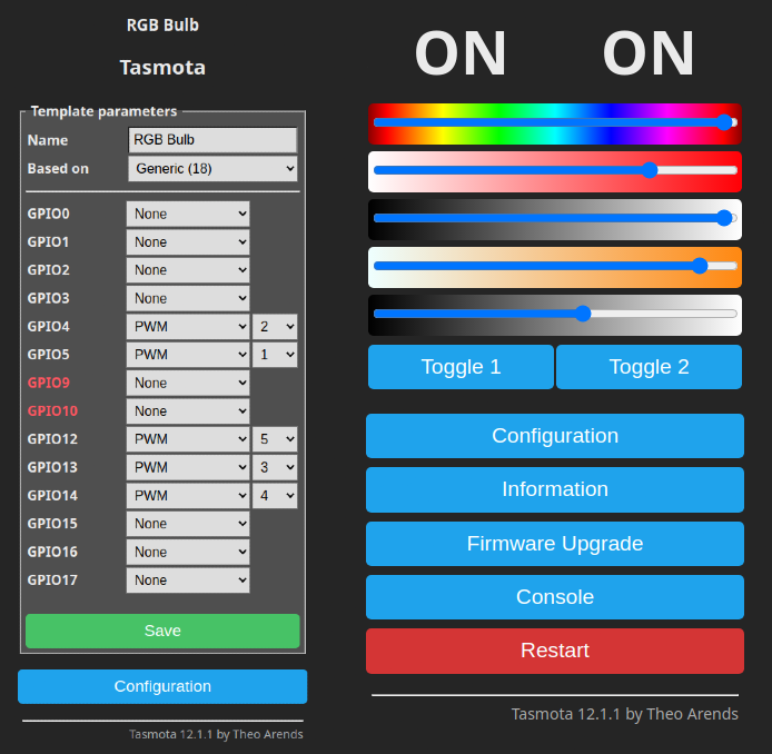 Final Configuration
Last thing I noticed was the bulb wouldn't retain its last colors and would stay off when powered off and powered on back. This was resolved after executing following commands under Tasmota:
SetOption0 1
PowerRetain 1
PowerOnState 3
There's ClapLights that goes well along with it!