Flashing Tasmota on LC Tech 5V 4CH Relay
05 Nov 2022
It seems we mostly require three components to put up non-smart home lights and other home electronics on a network:
- Relay
- A microcontroller with Wi-Fi capabilities
- AC to DC converter (to supply power to the microcontroller and relay)
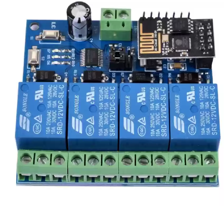 LC Tech 5V 4CH Relay
This relay has all other components except for a built-in AC to DC converter. It uses ESP8266 ESP-01S as a microcontroller and came pre-flashed with some firmware whose dump is available here. The ESP-01S on this board receives commands through the network and simply passes them (making use of RX/TX pins through a serial connection) to another chip present on this board which in turn actually controls the relays.
The pre-flashed firmware had a couple of issues which are summarized nicely in alternate firmware called RemoteRelay:
Why another firmware ?
This board is not using the ESP8266 to manage the relays but instead another onboard MCU. The ESP8266 module is just used as a WiFi interface with its default AT firmware. The two chips are using serial (115200-8-1) to communicate.
The original user experience is pretty clunky and no really usable. On power up, the board start an access point you need to connect your phone to in order to send commands. This is only usefull for testing as it's isolated from your main network.
To switch to station mode, you need to push a button on the board (S1), install an app on your phone and then use this app to feed your SSID and password to the board. The app will then display its IP. Once connected, you need to send a binary payload over a plain TCP socket. No HTTP, no protocol of any kind, just plain binary.
For example, you can run this command from Linux to switch on the first relay :
echo -ne "\xA0\x01\x01\xA2" | nc 192.168.0.9 8080There is no way to get a feedback of the current state of the relay (beside looking at the leds on the board).
On power loss, the board switch back to access point and you have to push the S1 button again to reconnect.
Wiring up
There are some most commonly used scenarios when wiring up the ESP-01S using a USB to TTL adapter:
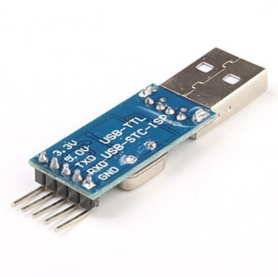 USB to TTL adapter
Runs the program present in flash:
| ESP-01S | USB to TTL | |--------- |------------ | | 3V3 | 3V3 | | GND | GND |
Runs the program present in flash and gain access to the serial console:
| ESP-01S | USB to TTL | |--------- |------------ | | 3V3 | 3V3 | | GND | GND | | RX | TX | | TX | RX |
Serial console can now be accessed using picocom:
$ picocom -b 76800 /dev/ttyUSB0
ESP-01S uses the default baud rate of 76800 to display boot messages. This may later be overridden by the program present in flash, if any.
Make sure you specify the correct baud rate otherwise you'll be sending and receiving garbled data. Experiment with these common baud rates used with ESP-01S if you're not sure of the expected baud rate:
9600 14400 19200 115200
If you're still getting garbled data, you'll have to do some research on the baud rate used by the firmware currently flashed on the microcontroller.
Booting into Flash Mode:
| ESP-01S | USB to TTL | |--------- |------------ | | 3V3 | 3V3 | | GND | GND | | EN | 3V3 | | IO0 | GND |
You'll have to make a few connections in parallel to boot into this mode. A breadboard might help.
Also there's no point booting into flash mode when you can't read and write to the flash. So, this mode is usually paired up with RX/TX connections.
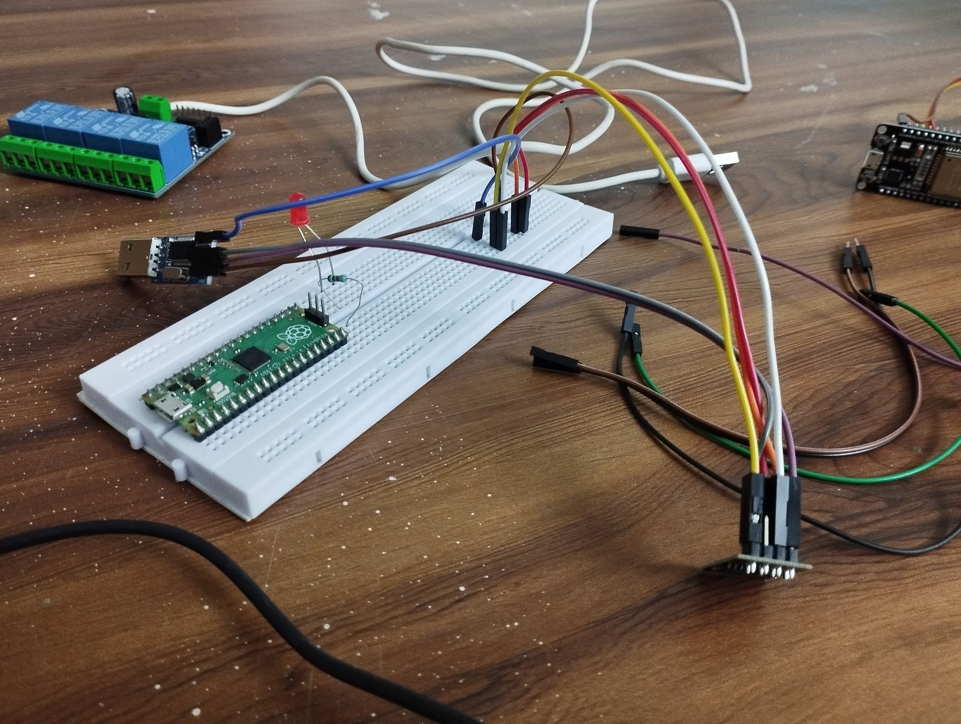
Booting into Flash Mode with access to Serial Console:
| ESP-01S | USB to TTL | |--------- |------------ | | 3V3 | 3V3 | | GND | GND | | EN | 3V3 | | IO0 | GND | | RX | TX | | TX | RX |
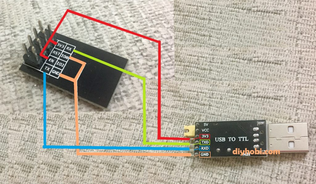 Wiring up to boot into Flash Mode with access to Serial Console
If you like, you can also make the following connection:
| ESP-01S | USB to TTL | |--------- |------------ | | RST | GND |
Plug in and out the RST jumper cable whenever you want to hard reset/reboot your chip (this won't erase the flash memory). If you don't setup this RST connection, I think re-plugging the 3V3 pin should have the same effect (happy to accept PR if you have an ESP-01S around at the moment to confirm).
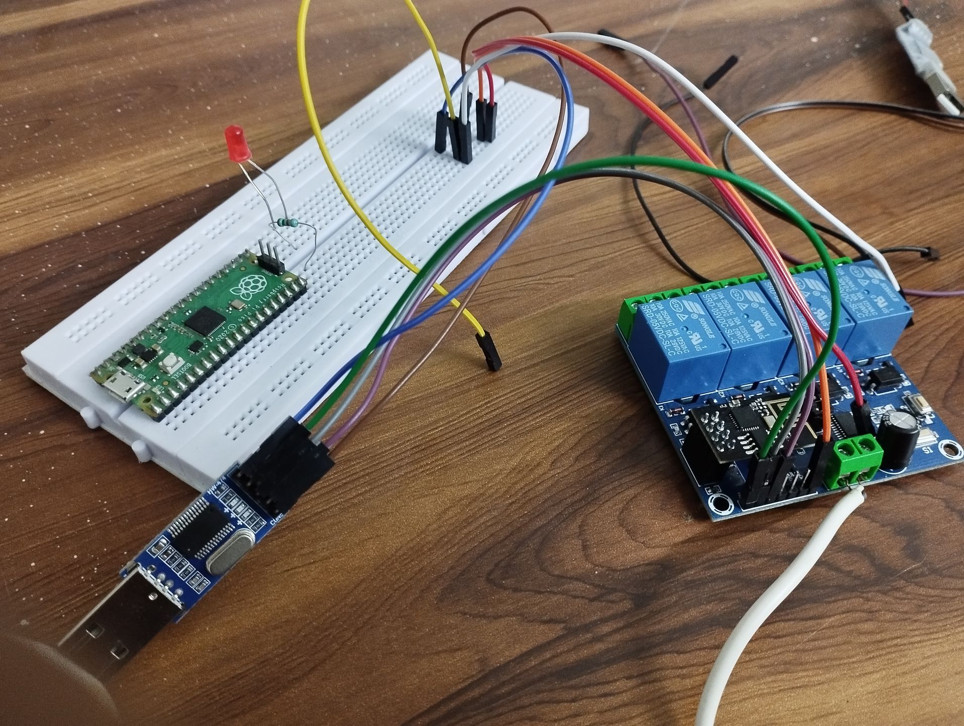 Connecting to pins on the relay board
 Connecting to pins directly on the ESP8266 ESP-01S
(Ignore the Pi Pico in above pics)
Now you should be able to read and write programs to flash memory. Let's start by taking a dump of what's already
present on the flash memory using esptool.py:
$ esptool.py --port /dev/ttyUSB0 --baud 115200 read_flash 0x00000 0x100000 /path/to/backup.bin
This will backup the first 1 MB from the flash memory. If you're using any other chip besides ESP-01S that has
a different flash size, adjust 0x100000 accordingly (e.g. set it to 0x400000 if chip has a flash size of 4 MB).
Flashing a custom firmware
RemoteRelay
I first flashed the chip with RemoteRelay as it it's made specifically for LC Tech Relays. You can compile and flash it using Arudino IDE. However, this firmware had an issue where it won't save the last relay state if the chip were to be rebooted. All relays would be set to OFF state after a reboot. This causes a problem that peripherals connected in relay under NO would always start as OFF and peripherals connected in relay under NC would always start as ON whenever the power goes off and comes back on, irrespective of the last relay state. Also, if you want to integrate RemoteRelay with HomeAssistant, you'll have to manually add API endpoints.
Tasmota
Next I went with Tasmota mostly in an attempt to load relay's last state in case of power reset that didn't seem
possible with RemoteRelay. Digging a bit, one way that worked for me is to compile Tasmota (using
tasmota-docker) with support for if logic conditions:
// user_config_override.h
#define USE_EXPRESSION         // Add support for expression evaluation in rules (+3k2 code, +64 bytes mem)
#define SUPPORT_IF_STATEMENT   // Add support for IF statement in rules (+4k2 code, -332 bytes mem)
$ docker run -ti --rm -v $(pwd)/Tasmota:/tasmota -u $UID:$GID blakadder/docker-tasmota -e tasmota-PT
This will output a .bin we can use to flash on the chip.
Let's erase the flash on the chip:
$ esptool.py --port /dev/ttyUSB0 erase_flash
and now write the generated .bin onto the chip:
$ esptool.py --port /dev/ttyUSB0 write_flash 0x00000 /path/to/tasmota.bin
Connect the ESP-01S back to the relay and power it on.
Now to make the ESP8266 communicate with the seconday chip which controls the actual realys, we'll
add some serial commands in Tasmota GUI. Applying the configuration and setting up rules from the 12V variant
seems to also work for my 5V variant:
https://templates.blakadder.com/LC-ESP01-4R-12V.html
Now to save and load relay's last state, create another rule:
rule2
on Power1#State=0 do mem1 0 endon
on Power2#State=0 do mem2 0 endon
on Power3#State=0 do mem3 0 endon
on Power4#State=0 do mem4 0 endon
on Power1#State=1 do mem1 1 endon
on Power2#State=1 do mem2 1 endon
on Power3#State=1 do mem3 1 endon
on Power4#State=1 do mem4 1 endon
on System#Boot do if (mem1==1) SerialSend5 A00101A2 endif endon
on System#Boot do if (mem2==1) SerialSend5 A00201A3 endif endon
on System#Boot do if (mem3==1) SerialSend5 A00301A4 endif endon
on System#Boot do if (mem4==1) SerialSend5 A00401A5 endif endon
on System#Boot do if (mem4==1) SerialSend5 A00401A5 endif endon
And enable it with:
rule2 1
The rules in the linked template and loading/saving statesmake sense if you connect all your peripherals to NO
on the relays.
If you'll be connecting all of them to NC, swap State=0 with State=1 and vice-versa in both rules like below:
rule1
on System#Boot do Baudrate 115200 endon
on SerialReceived#Data=41542B5253540D0A do SerialSend5 5749464920434f4e4e45435445440a5749464920474f542049500a41542b4349504d55583d310a41542b4349505345525645523d312c383038300a41542b43495053544f3d333630 endon
on Power1#State=0 do SerialSend5 A00101A2 endon
on Power1#State=1 do SerialSend5 A00100A1 endon
on Power2#State=0 do SerialSend5 A00201A3 endon
on Power2#State=1 do SerialSend5 A00200A2 endon
on Power3#State=0 do SerialSend5 A00301A4 endon
on Power3#State=1 do SerialSend5 A00300A3 endon
on Power4#State=0 do SerialSend5 A00401A5 endon
on Power4#State=1 do SerialSend5 A00400A4 endon

rule2
on Power1#State=0 do mem1 1 endon
on Power2#State=0 do mem2 1 endon
on Power3#State=0 do mem3 1 endon
on Power4#State=0 do mem4 1 endon
on Power1#State=1 do mem1 0 endon
on Power2#State=1 do mem2 0 endon
on Power3#State=1 do mem3 0 endon
on Power4#State=1 do mem4 0 endon
on System#Boot do if (mem1==1) SerialSend5 A00101A2 endif endon
on System#Boot do if (mem2==1) SerialSend5 A00201A3 endif endon
on System#Boot do if (mem3==1) SerialSend5 A00301A4 endif endon
on System#Boot do if (mem4==1) SerialSend5 A00401A5 endif endon
on System#Boot do if (mem4==1) SerialSend5 A00401A5 endif endon
Make sure to enable both these rules:
rule1 1
rule2 1
If you noticed above in rule2, for some reason I had to repeat the last line:
on System#Boot do if (mem4==1) SerialSend5 A00401A5 endif endon
otherwise Tasmota 12.2.0.2 didn't seem to pick it up.
Still need to verify if it's me messing something up or if this seems a bug in Tasmota.