Flashing OpenBeken on 3-pin Wi-Fi switch based on BC101VE-11P (BK7238)
27 Jul 2025
I received this 3-pin Wi-Fi switch costing INR 500 that lets me control power to the connected appliance through the vendor's proprietary Android app. It works fine. It looks to be based on Tuya as I am also able to pair up the switch to the Smart Life Android app.
 The switch
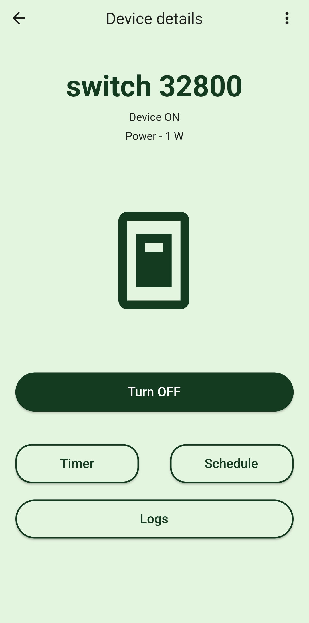 Vendor's Android app
(The switch doesn't have energy monitoring circuitry
but the app shows 1W as a placeholder anyway)
I wanted to see I could cut the cloud as well as flash a more open firmware to it. I started off with tuya-convert. It didn't work cause the peripheral is based on a newer firmware that isn't supported by tuya-convert. I went ahead to disassemble it to inspect it better.
Disassembly
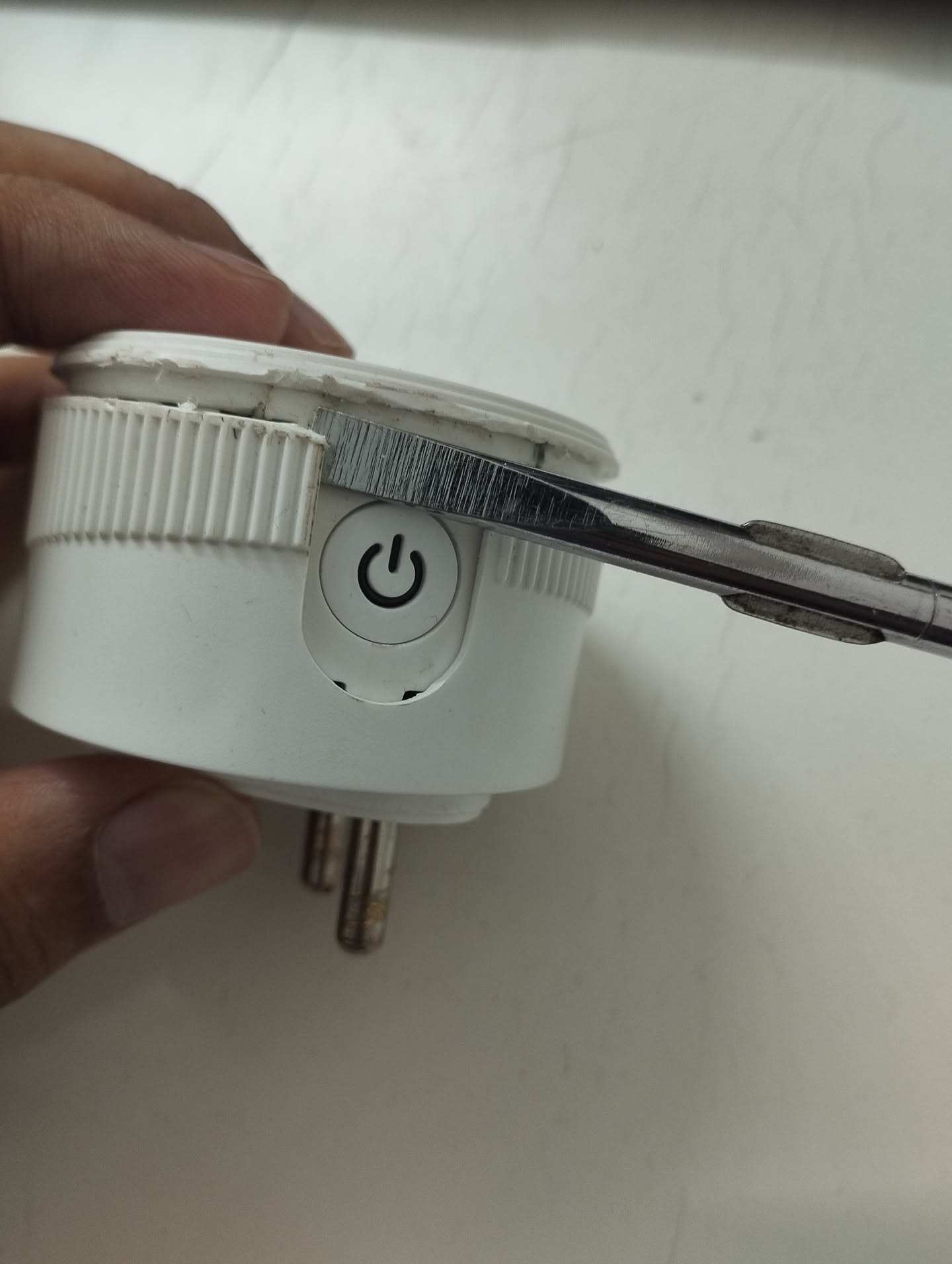
I basically did something like this:
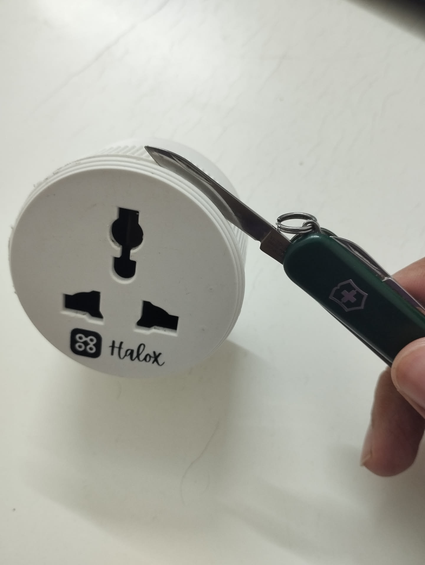 Insert and run a knife or a sharp object around the
edges to cut through any hardened glue
 Apply pressure on both the exposed ends with a blunt
object and pry it open carefully
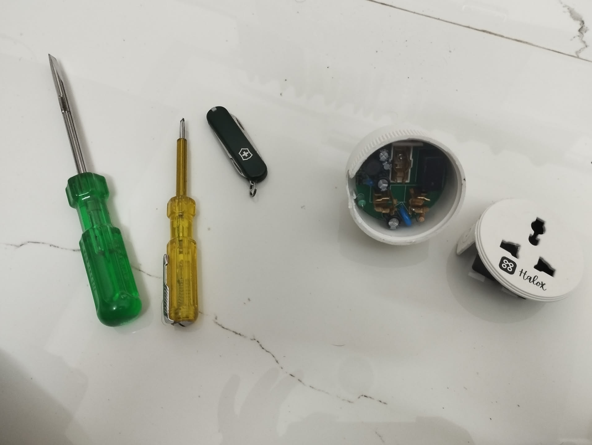 Opened carefully
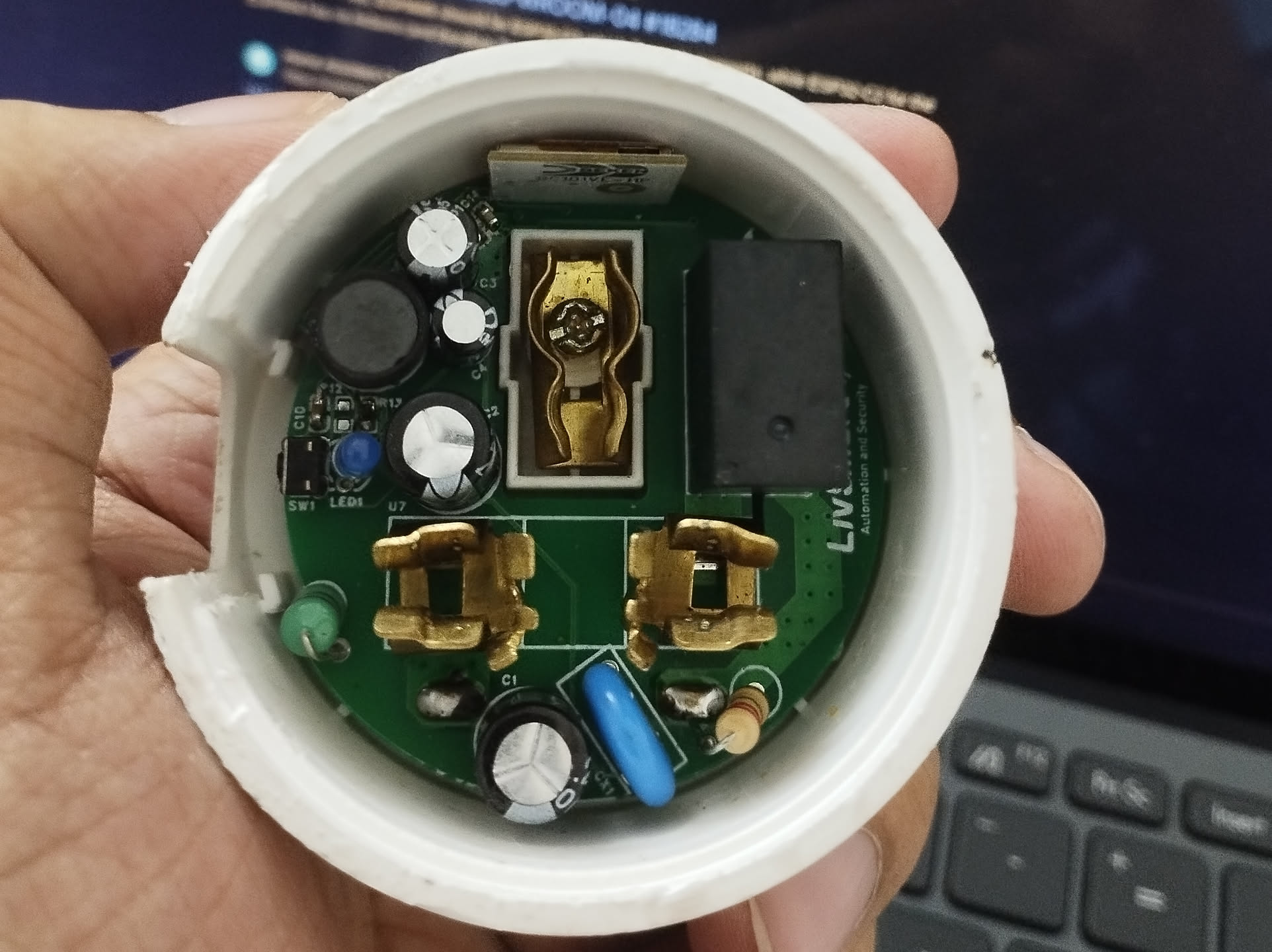 Clearer
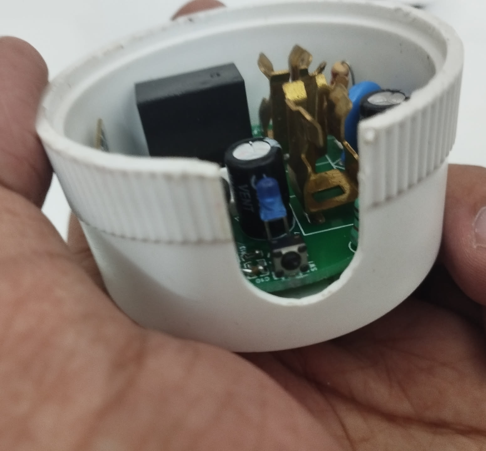 Lift the circuit board by inserting a screwdriver or a small
object through the small gap and applying force
just above the plastic casing
 Ok, lifted successfully
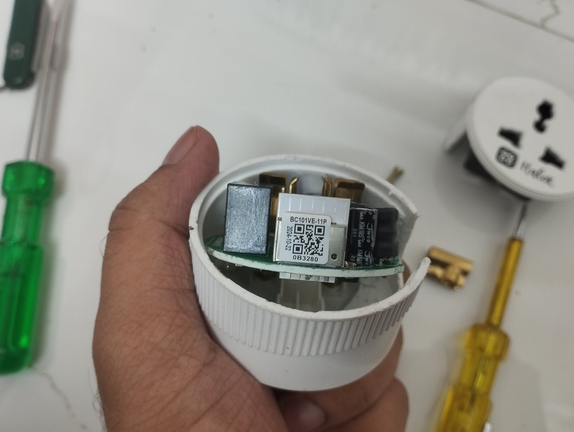
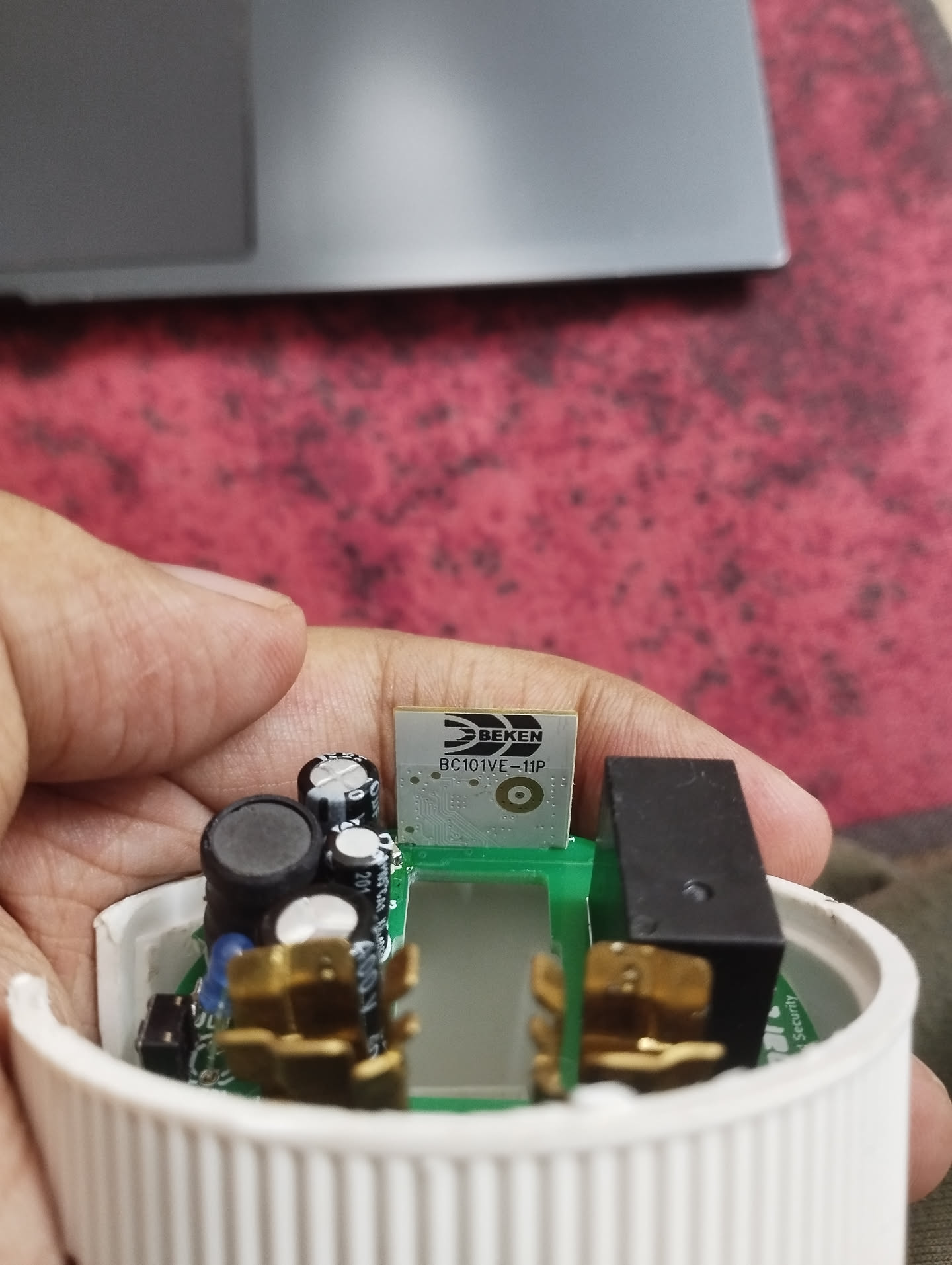
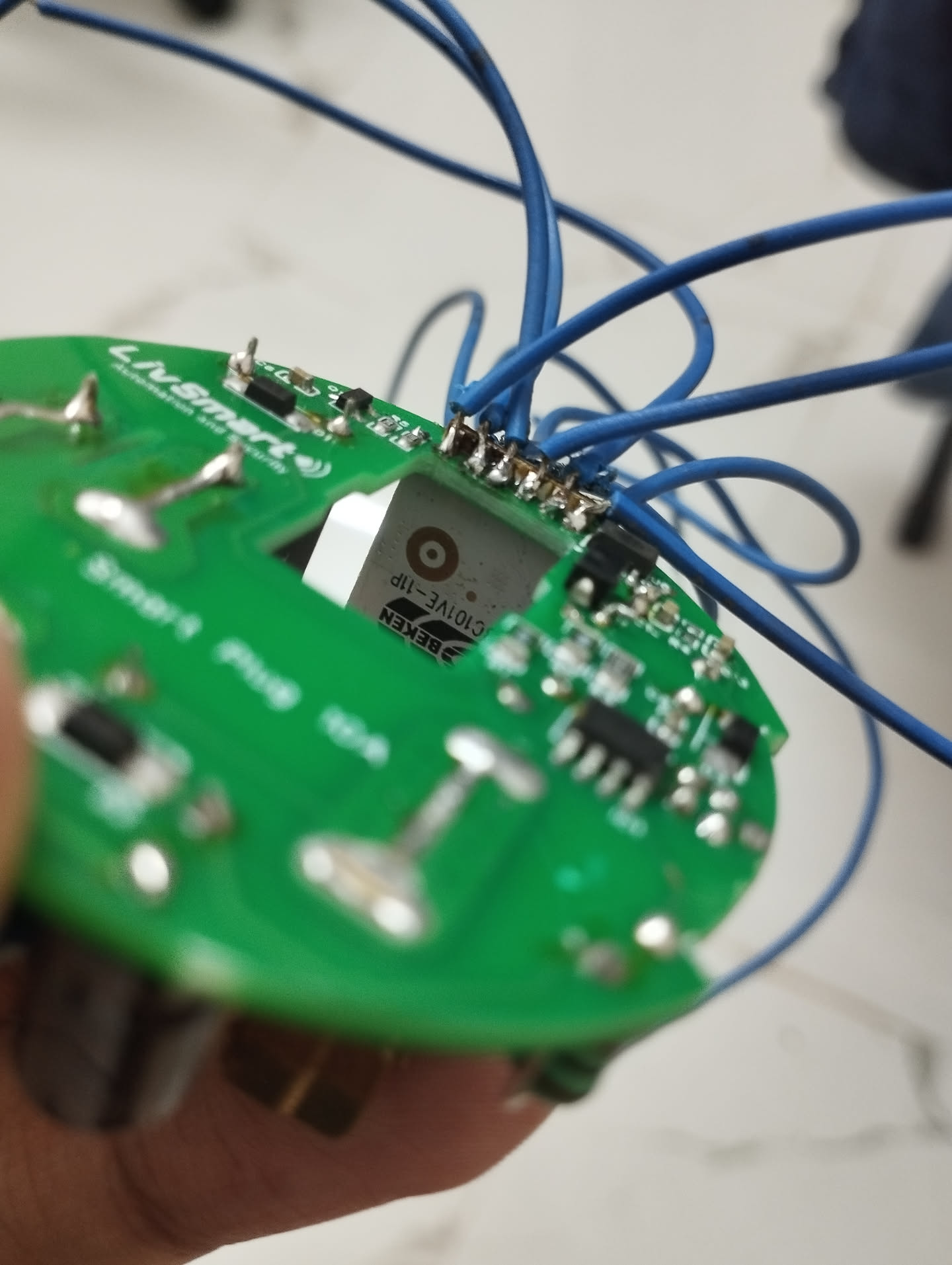
The sticker on the SoC reads "BC101VE-11P".
Beken BC101VE-11P
Looking up on this SoC, I found this page by Cionlabs, who looks to be the manufacturer
of the BC101VE-11P SoC:
https://cionlabs.com/product/bc101ve-11p/
Interesting points to note on the page:
BC101VE-11P based on BK7238
ESP8685-WROOM-03 Pin compatible
Digging further into these points, it looks like the SoC isn't an ESP MCU (which I'm previously familiar with). It also looks like Tasmota doesn't support BK7238 at the time of writing this. However, it does mention about pins being compatible with ESP8685-WROOM-03 and there's a Tasmota-like alternative called OpenBeken available for this SoC.
I also found this datasheet on the BC101VE-01-11P from cionlabs here (wonder if it's for
the same MCU, cause mine just mentions BC101VE-11P):
https://cionlabs.com/wp-content/uploads/2025/06/BC101VE-01-11P-V1.4.pdf
It features this pin layout:
 Pin layout of the BC101VE-01-11P from the official datasheet
Also looking up on the ESP8685-WROOM-03, I found this PDF datasheet from Espressif which
illustrates its pin layout schematic:
https://www.espressif.com/sites/default/files/documentation/esp8685-wroom-03_datasheet_en.pdf
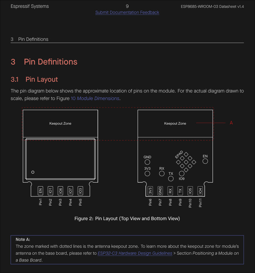 Illustration of ESP8685-WROOM-03's pin layout schematic
Note: It looks like this SoC by Espressif was previously referred to as ESP8685-WROOM-03 but has since joined the ranks of ESP32 fam and this same SoC is now also known as ESP32-C3.
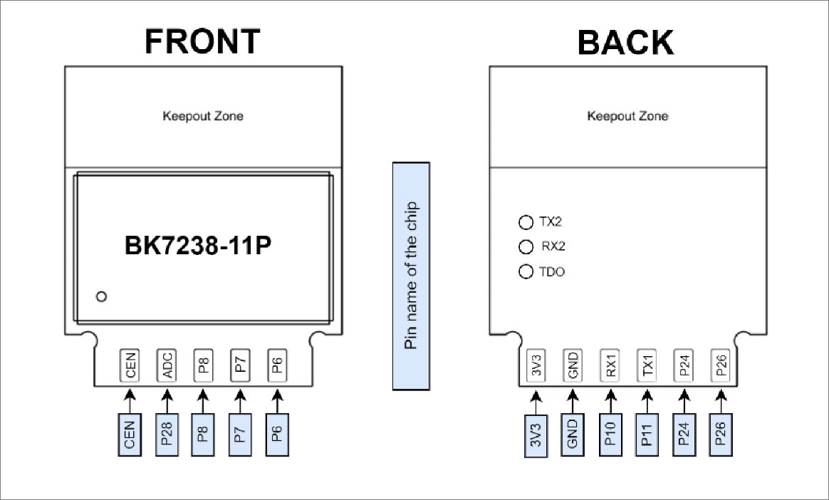
The top and bottom pin layout on the official datasheet as well as the ESP8685-WROOM-03 seems to match with what I have on my BC101VE-11P (5 pins on the top side and 6 pins on the bottom side) as in the picture:
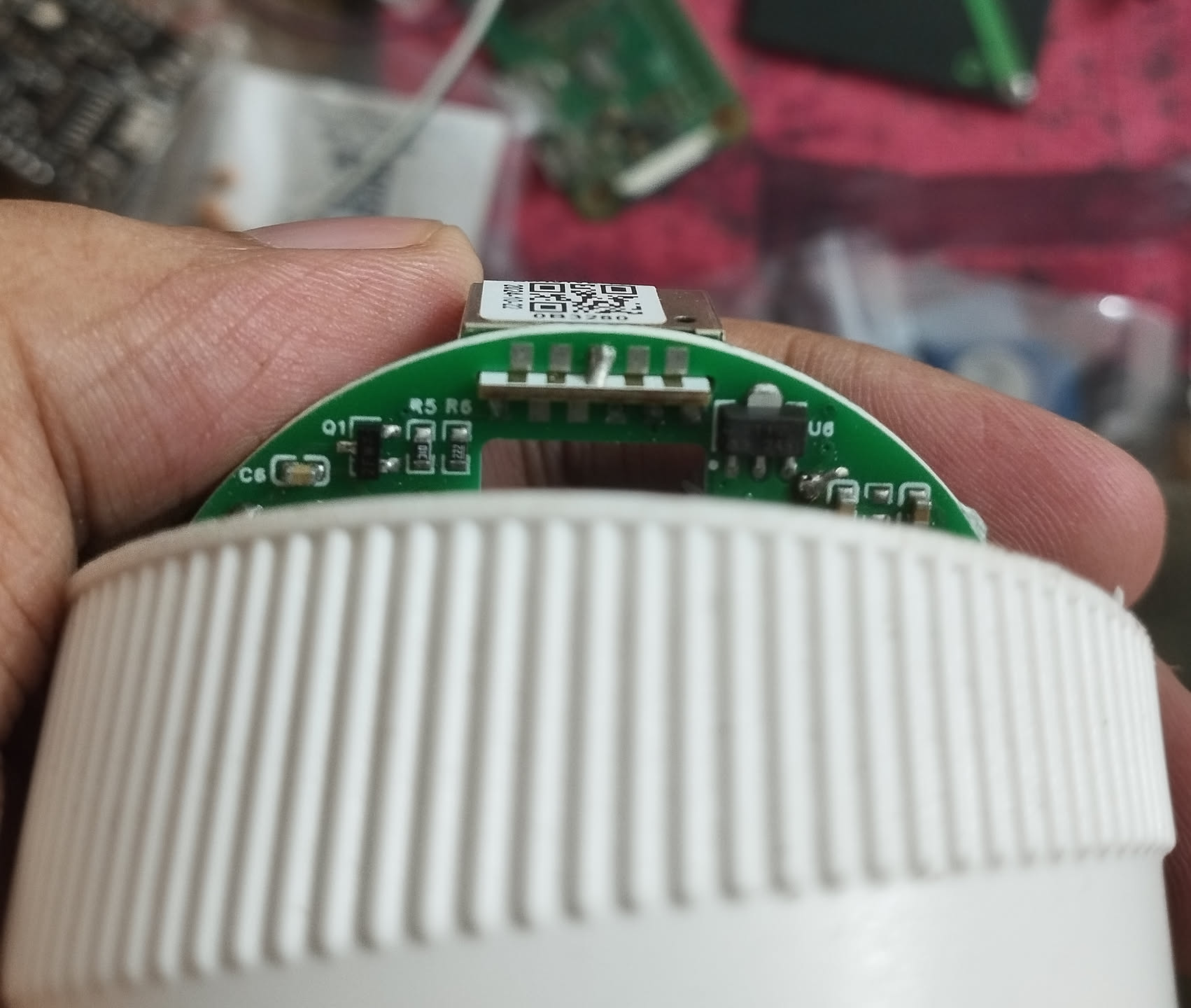 Top and bottom pin layout on my BC101VE-11P
However, the layout of the test pins on the bottom side neither matches with what I have on
my BC101VE-11P from the switch (mine aren't aligned in the same way as TX2, RX2, TDO
are in this picture), nor does it match with the ESP8685-WROOM-03.
 Test pin layout on my BC101VE-11P
UART
On the first glance, it looks all the pins on the SoC that we need to have in contact to form
a UART serial connection are consistent in the pin layout:
- 3v3
- GND
- RX
- TX
All the 4 pins are present on bottom side on both the SoCs.
UART can be established using another machine through a USB to TTL adapter.
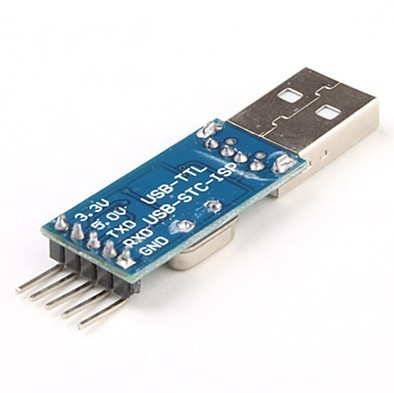 USB to TTL adapter
It's a good idea to power up BC101VE-11P module now using the USB to TTL adapter to make sure it's still operable after the plastic surgery. Don't need to solder anything yet. Get a few jumper cables and form up connections through temporary contact as described:
| BC101VE-11P | USB to TTL |
|---|---|
| 3V3 | 3V3 |
| GND | GND |
This should power up the module and I could see the blue onboard LED on the smart switch board flash once and turn off. It's got some life, cool!
Ok, let's try if we can see anything over UART. May want to consider soldering wires to the BC101VE-11P at this point. For now I had a coworker help me out with making temporary contacts (buying out some buffer tehee):
| BC101VE-11P | USB to TTL |
|---|---|
| 3V3 | 3V3 |
| GND | GND |
| RX | TX |
| TX | RX |
On my Linux laptop connected over UART, the device showed up as /dev/ttyACM0. It could
instead also show up as /dev/USB0 or something. Verify once.
Setting the baud rate to 115200 with picocom seems to have worked:
$ picocom -b 115200 /dev/ttyACM0
It also helps that my (and most other) USB to TTL devices flash a different LED whenever data is being emitted over serial.
I noticed my BC101VE-11P module flash the blue LED once and spew these logs over serial everytime I powered it up:
go os_addr(0x10000)..........
BK7238_1.0.14
REG:cpsr        spsr        r13      BK7238_1.0.14
REG:cpsr        spsr        r13         r14
SVC:0x000000D3              0x00401C1C  0x000033A0
IRQ:0x000000D2  0x00000010  0x00401E0C  0x2C00B449
FIR:0x000000D1  0x00000010  0x00401FFC  0x3289416B
SYS:0x000000DF              0x0040192C  0x00000158
ST:0x00000000
[I/FAL] Fal(V0.4.0)success
                          [I/OTA] RT-Thread OTA package(V0.2.8-beken-1133282d-20220604) initialize success.


go os_addr(0x10000)..........

FATAL: read zero bytes from port
term_exitfunc: reset failed for dev UNKNOWN: Input/output error
And then it'd go silent afterwards and /dev/ttyACM0 device file would disappear.
I guessed it to be a power issue or a bad USB to TTL adapter. I had a spare NodeMCU ESP8266 development board that I had flashed Tasmota onto a while ago but hadn't configured it any further, so it'd still be broadcasting tasmota's default AP when it's powered on properly.
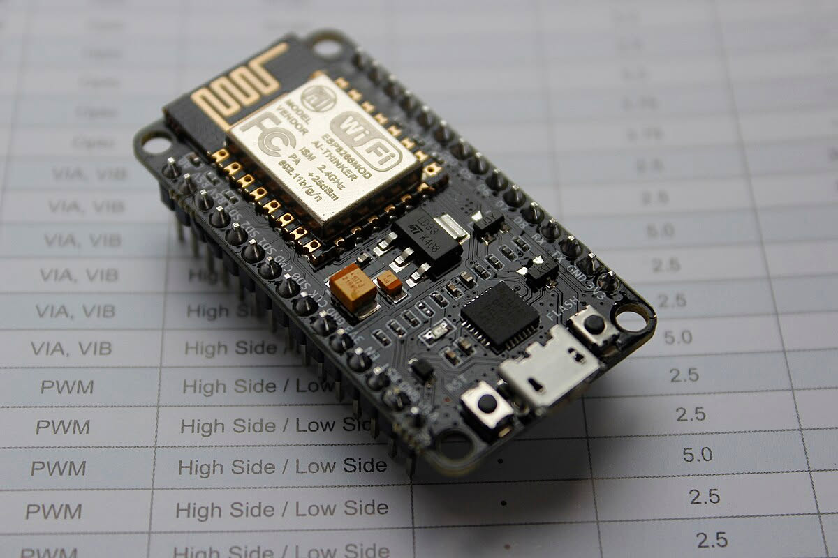 NodeMCU ESP8266 Development Board
I tried to power up the NodeMCU through the 3v3 rail:
| NodeMCU ESP8266 | USB to TTL |
|---|---|
| 3V3 | 3V3 |
| GND | GND |
And the tasmota's AP didn't show up either! Although, powering it up through the 5V rail seems to have worked and I could see tasmota's AP and connect over to 192.168.4.1 on the AP just fine:
| NodeMCU ESP8266 | USB to TTL |
|---|---|
| 5V | 5V |
| GND | GND |
So, it's very likely a power issue where my machine's USB port or the USB to TTL adapter isn't able to compensate for the additional demand in current when the voltage is lowered to 3.3V, in order to supply the same power as on a 5V rail.
Sadly the BC101VE-11P accepts only 3.3V input and not a 5V input. For the sake of it, I decided to power up the BC101VE-11P module over 3.3V but with the USB to TTL now connected to a wall adapter:
| BC101VE-11P | USB to TTL |
|---|---|
| 3V3 | 3V3 |
| GND | GND |
Noticed a slight change in the behaviour of the blue onboard LED this time. The LED now blinked every second instead of previously flashing once and shutting down when connected to my machine over USB. This behaviour was consistent.
Decided to give another try to power up my spare NodeMCU ESP8266 through the 5V rail on my USB to TTY adapter connected to my machine's USB port where the NodeMCU would in-turn power up the BC101VE-11P through one of the 3V3 output pins present on the development board:
| NodeMCU ESP8266 | USB to TTL |
|---|---|
| 5V | 5V |
| GND | GND |
| NodeMCU ESP8266 | BC101VE-11P |
|---|---|
| 3V3 | 3V3 |
| GND | GND |
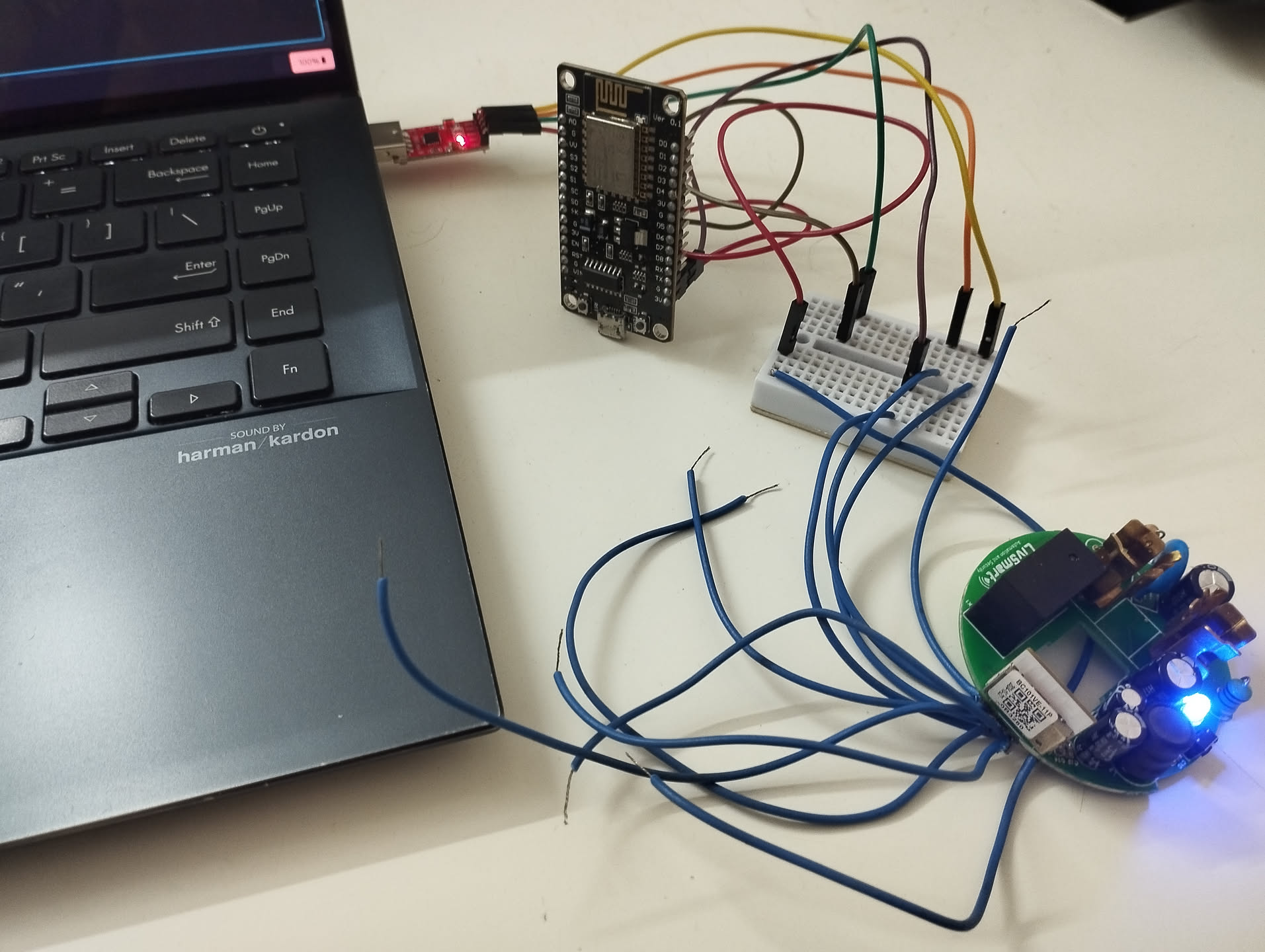
This gave me a solid light up of blue LED onboard. Additionally, hooking up the RX and TX connections directly to the BC101VE-11 from my USB to TTL looked to be giving logs properly over serial now:
| BC101VE-11P | USB to TTL |
|---|---|
| RX | TX |
| TX | RX |
$ picocom -b 115200 /dev/ttyACM0

go os_addr(0x10000)..........
[garbled output]start addr:0x4114d0, size:191280
[Flash]id:0x854215
--write status reg:4004,1--
[Flash]init over
sctrl_sta_ps_init
SDK Rev: 3.0.70 d414331
[THD]app:[tcb]4127b0 [stack]4117a8-4127a8:4096:0
[THD]extended_app:[tcb]413020 [stack]412818-413018:2048:4
[THD]idle:[tcb]413490 [stack]413088-413488:1024:0
[THD]timer_thd:[tcb]414218 [stack]413610-414210:3072:2
OSK Rev: F-3.0.44 d414331
cset:0 0 0 0
[FUNC]rwnxl_init
chip id=7238 device id=22068000
IP Rev: W4-3.0.70-P0
txdesc flush
[FUNC]intc_init
[FUNC]calibration_main
device_id=0x22068000
calibration_main over
flash txpwr table:0xf
dif g and n20 ID in flash:4
read txpwr tab from flash success
uncali adc value:[00 00 00]
temp in flash is:253
[THD]temp_detct:[tcb]414830 [stack]414428-414828:1024:3
lpf_i & q in flash is:76, 78
xtal in flash is:83
xtal_cali:83
--init_xtal = 83
[FUNC]ps_init
int watchdog enabled, period=10000
task watchdog enabled, period=60000
[FUNC]func_init_extended OVER!!!

start_type:0
[THD]kmsgbk:[tcb]4158f8 [stack]4148f0-4158f0:4096:6
[THD]init_thread:[tcb]416138 [stack]415960-416130:2000:0
[THD]core_thread:[tcb]417000 [stack]4167f8-416ff8:2048:7
[THD]rf_arbitrate:[tcb]417968 [stack]417160-417960:2048:8
rf_thread_init ok
[THD]ble:[tcb]418a80 [stack]417a78-418a78:4096:5
ble mac:a0-24-42-0b-32-81
rwip_heap_env addr:0x418ae8 size:4044
rwip_heap_db addr:0x419ac0 size:3084
rwip_heap_msg addr:0x41a6d8 size:10364
rwip_heap_non_ret addr:0x41cf60 size:668
xvr_reg_init
tx_pwr_idx:20
enter normal mode
[gapm_cmp_evt_handler] conidx:0,operation:0x1,status:0x0
cmd->addr.addr[5] :0
[gapm_cmp_evt_handler] conidx:0,operation:0x3,status:0x0
gapm_cmp_evt:GAPM_SET_DEV_CONFIG
gapm_cmp_evt:wait GAPM_GEN_RAND_NB
[gapm_cmp_evt_handler] conidx:0,operation:0x33,status:0x0
gapm_cmp_evt:GAPM_GEN_RAND_NB
[gapm_cmp_evt_handler] conidx:0,operation:0x33,status:0x0
gapm_cmp_evt:GAPM_GEN_RAND_NB
[gapm_cmp_evt_handler] conidx:0,operation:0x5,status:0x0
gapm_cmp_evt:BLE_STACK_OK
[THD]cli:[tcb]41fc50 [stack]41ec48-41fc48:4096:3
Initializing TCP/IP stack
tcp_port:60670
[THD]tcp/ip:[tcb]4129d8 [stack]417160-417960:2048:7
[THD]wp�BK7238_1.0.14
REG:cpsr        spsr        r13         r14
SVC:0x000000D3              0x00401C1C  0x000033A0
IRQ:0x000000D2  0x00000010  0x00401E0C  0x2C049409
FIR:0x000000D1  0x00000010  0x00401FFC  0x3289506B
SYS:0x000000DF              0x0040192C  0x00000158
ST:0x00000000
[I/FAL] Fal(V0.4.0)success
                          [I/OTA] RT-Thread OTA package(V0.2.8-beken-1133282d-20220604) initialize success.
I got the above logs from the stock vendor firmware present on thGe BC101VE-11P. It mentions
Initializing TCP/IP stack and tcp_port:60670 (pretty much used by Tuya) which hints that
the module is powered up and operating properly. I could also see the module showing up as
"online" in the vendor shipped Android app at this point.
Flashing OpenBeken
So far so good with the pins on BC101VE-11P matching with the ones mentioned in the official documentation as well as present on ESP8685-WROOM-03.
Now to find out what pin boots the BC101VE-11P into UART flash/download mode. This doesn't seem to be clearly documented in the official datasheet.
The datasheet on the ESP8685-WROOM-03 by Espressif mentions the following:
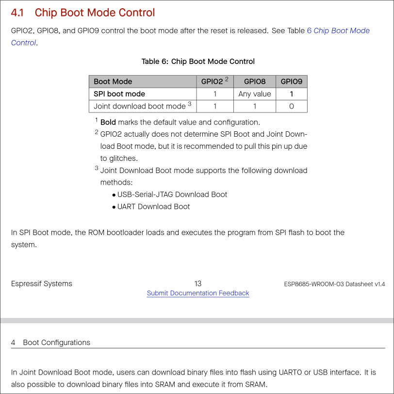 Chip Boot Mode Control on ESP8685-WROOM-03
Which doesn't make much sense as there's no pin labelled as GPIO8 on my BC101VE-11P (what pin should I pull-up/provide 3.3V to for booting into joint download boot mode?).
I also came across this document on ESP8685-WROOM-03:
https://fcc.report/FCC-ID/2AC7Z-ESP868503/5612045.pdf
It mentions:
IO9 is internally logic high. If IO9 is set to pull-up, the Boot mode is selected. If this pin is pull-down or left floating, the Download mode is selected. For more information on ESP8685-WROOM-03, please refer to ESP8685-WROOM-03 Datasheet.
Okay, both the above sources mention about pulling-down GPIO9 to for download mode. Let's just try this and forget about the GPIO8 for now. However, as I mentioned before, the test pin points present in the middle of the SoC do not the match between both the modules. This is inconvenient because now I'm not sure what pin on the BC101VE-11P corresponds to GPIO9.
I got the top and bottom pins soldered on the module from a local shop to make everything manageable. The necessary ones are 3V3, GND, RX, TX.
 Some nice soldering!
And then connecting the pins all over again:
| NodeMCU ESP8266 | USB to TTL |
|---|---|
| 5V | 5V |
| GND | GND |
| NodeMCU ESP8266 | BC101VE-11P |
|---|---|
| 3V3 | 3V3 |
| GND | GND |
| BC101VE-11P | USB to TTL |
|---|---|
| RX | TX |
| TX | RX |
 Yay it works!
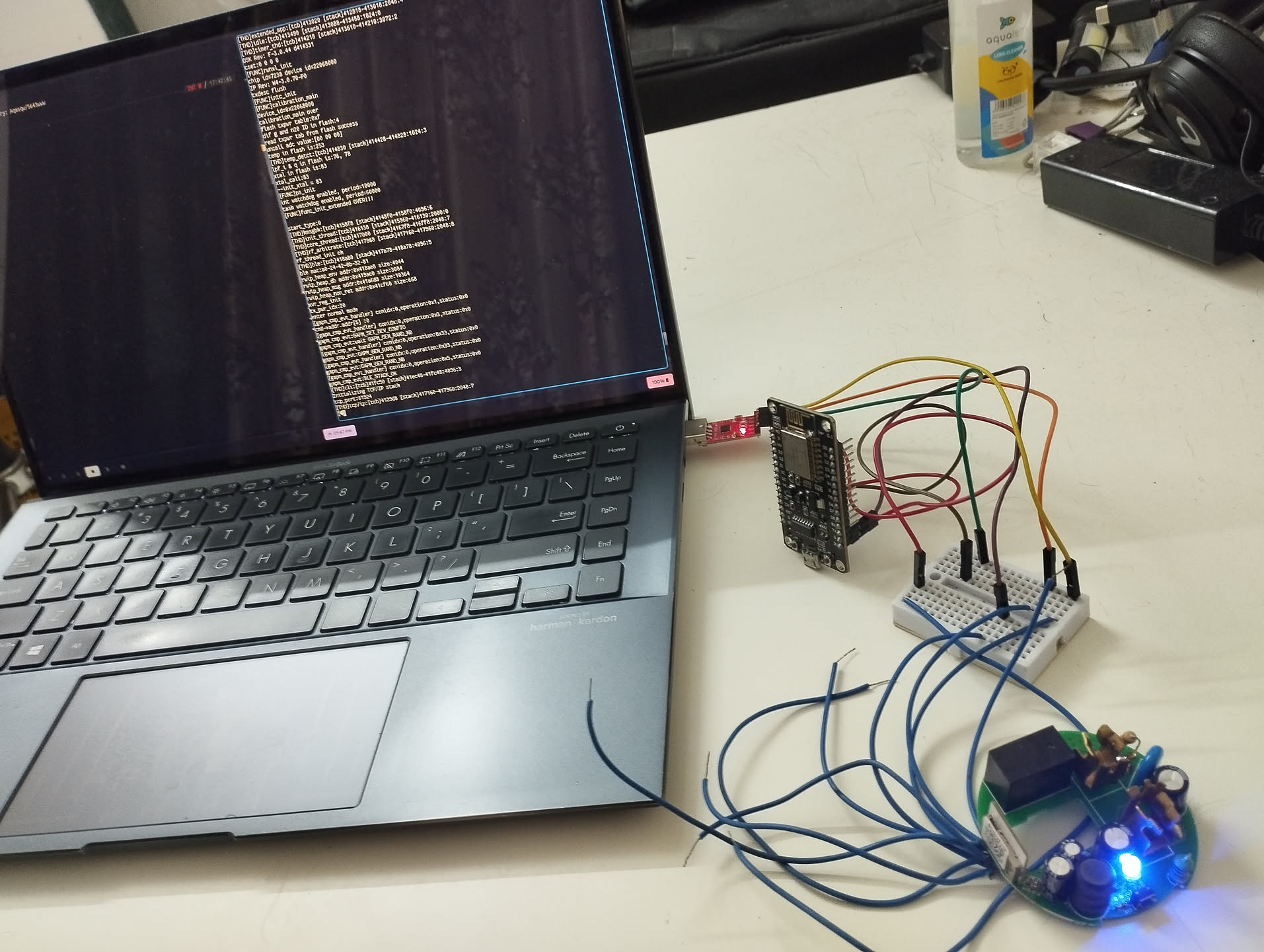 UART logs show up fine as well
I had to do some experimenting to try to boot the module into download mode. I connected the module to my lappy through UART and ran a loop to try dump the firmware from the flash:
$ while true; do sudo bk7231tools read_flash -d /dev/ttyACM0 -s 0 -l 0x200000 switch_stock_fw.bin; sleep 1s; done
The 0x200000 because BC101VE-11P is mentioned to have 2MB of flash storage.
Then I pulled-down each of the test pins using my fingers to bring one end of the jumper cable in contact with GND temporarily, and then rebooting the module (by re-connecting 3V3 or GND). One pin at a time.
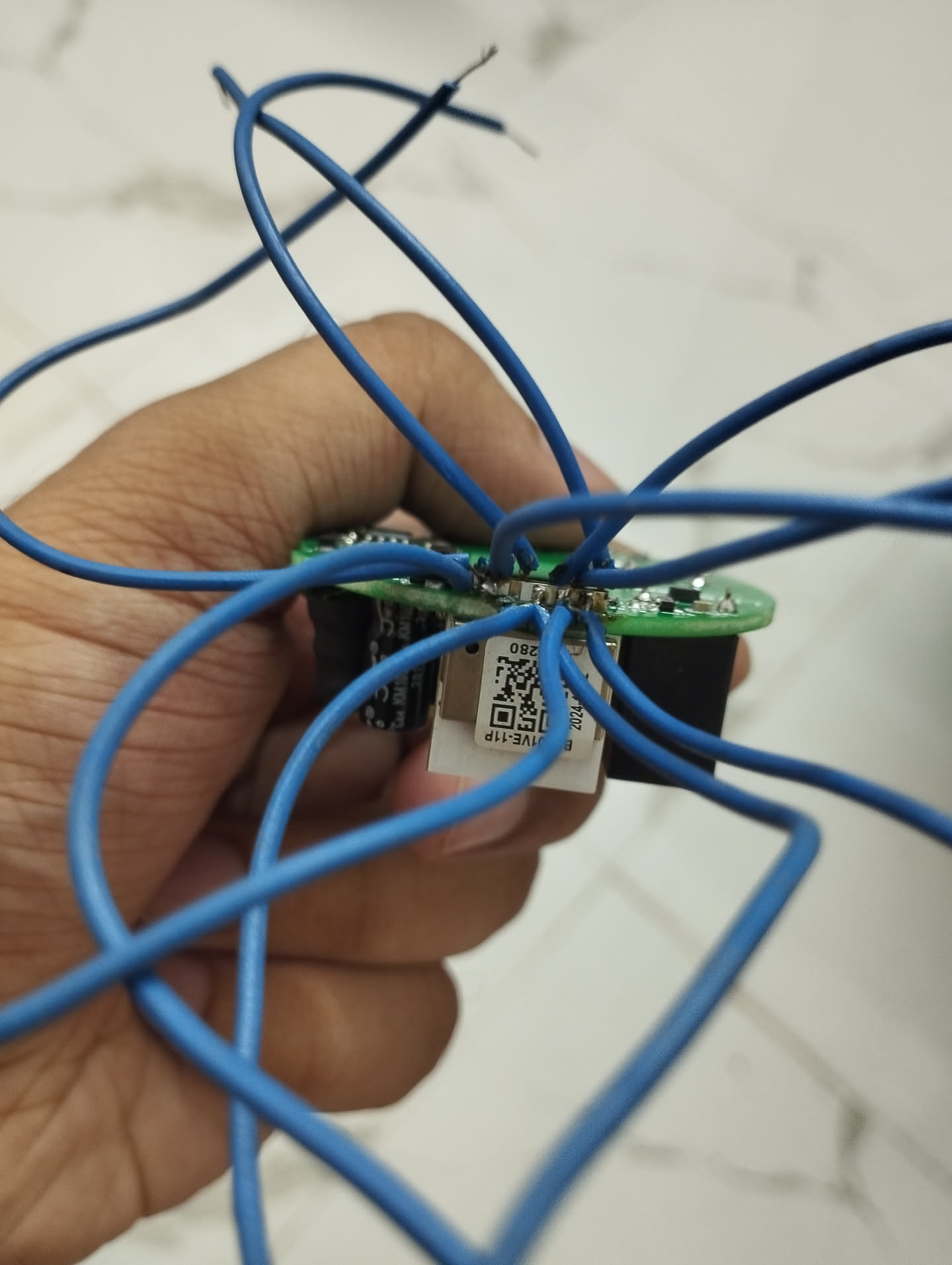
After some fighting, I found that pulling-down one of the following points (as circled orange in the picture below) allowed my lappy to dump the flash! This means the module went into download mode.
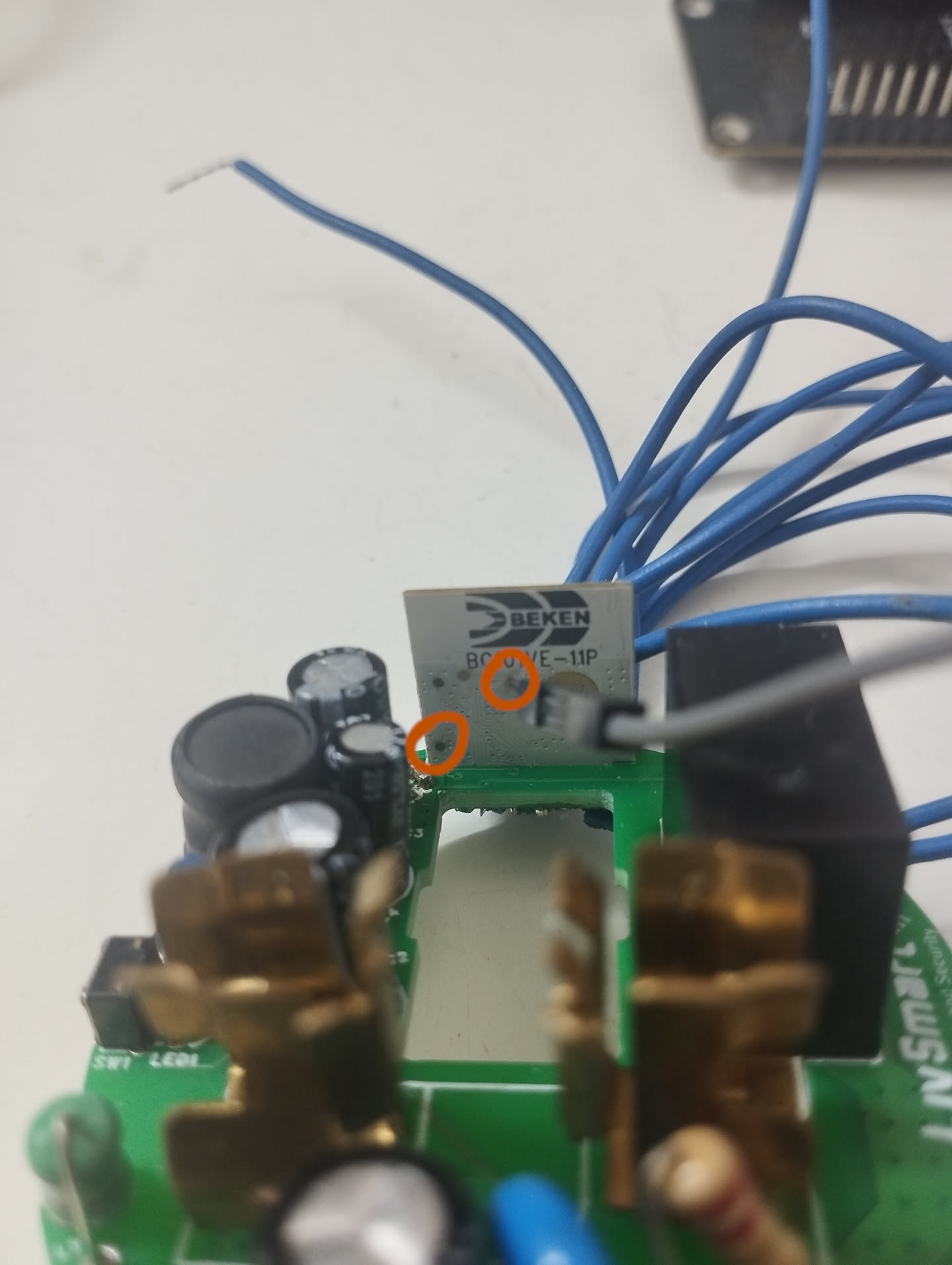 Pulling-down one of these pins causes the
module to boot into download mode
So to boot into download mode, additionally make one of these contacts:
| NodeMCU ESP8266 | BC101VE-11P |
|---|---|
| GND | <Unknown Pin-1> |
| GND | <Unknown Pin-2> |
Sometimes if one of the encircled pin didn't work, then the other encircled pin worked into booting the module into download mode most times.
Once I had a backup of the stock firmware done, I downloaded the latest OpenBeken release for
BK7238 for UART Flash from:
https://github.com/openshwprojects/OpenBK7231T_App/releases
and flashed it onto my module using:
$ sudo bk7231tools write_flash -d /dev/ttyACM0 -s 0 -S 0 OpenBK7238_QIO_1.18.138.bin
I had to also to pass -B flag to overwrite the bootloader. Before deciding to overwrite the
bootloader, make sure you've taken a dump of the stock firmware. This is supposed to be risky.
After the flashing was performed successfully, I rebooted the module into normal mode. Post this I am unable to see any logs through UART. However, an access point with its SSID "OpenBK7238_xxxxxxxx" did start to show up. Connecting to it and accessing 192.168.4.1 in the webbrowser looks to have worked!
[TBD] Configuration
[Need to work on this section]
I configured OpenBeken to connect to my Wi-Fi router. OpenBeken offers a GPIO testing tool under the Launch Web Application option accessible through the OpenBeken webserver running on the module. I figured the blue LED is connected invertedly to GPIO6 and the push button on the switch is connected to GPIO10.
I still need to figure out what GPIO pin the relay is connected to, something I'll be able to do when I can get the plastic enclosure up and connect it 220V AC using pogo pins, which I believe should power up the relay.
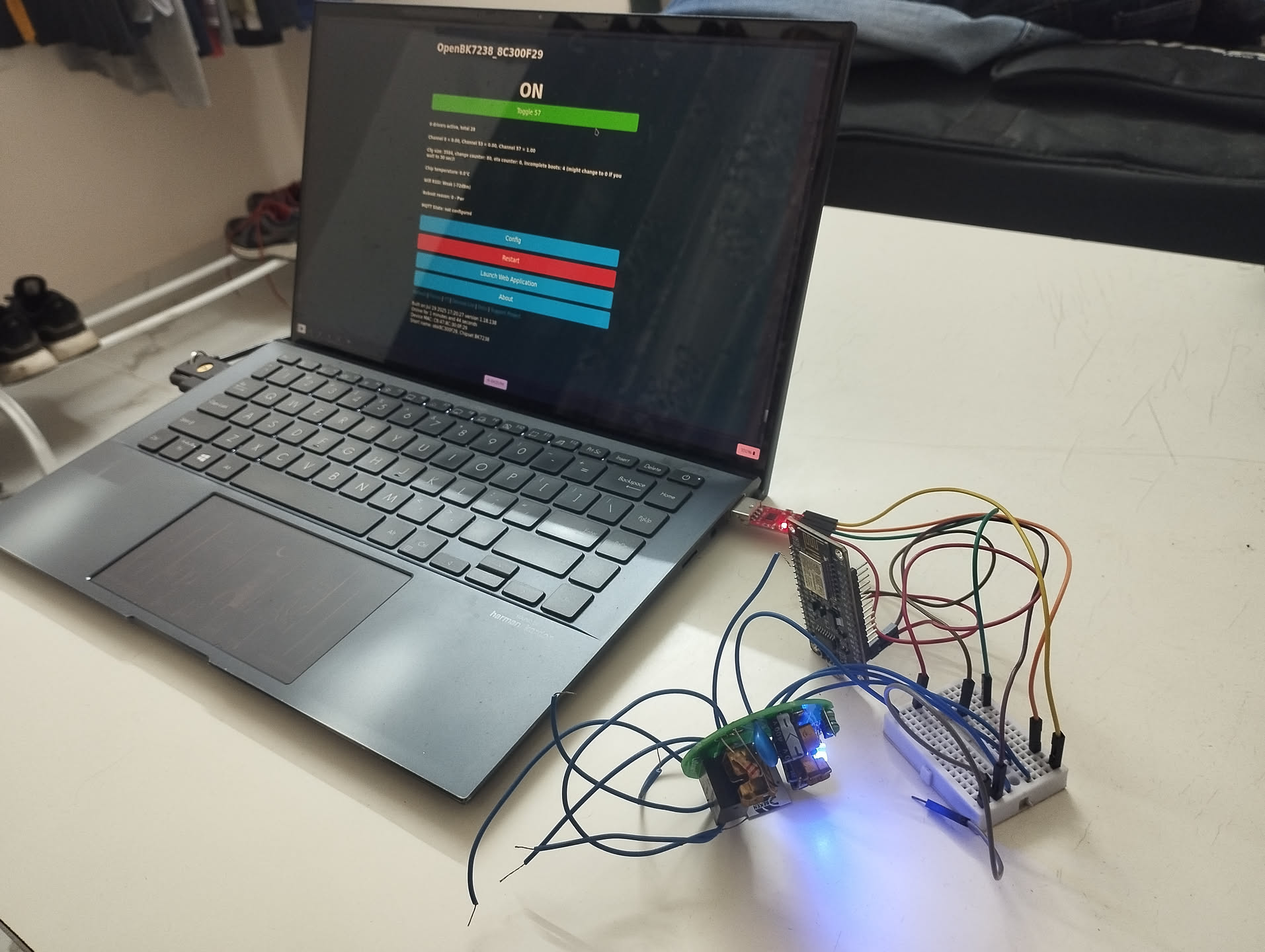 My switch running OpenBeken v1.18.138
This is the configuration that shows up on my Web Application as of now:
{
  "vendor": "Tuya",
  "bDetailed": "0",
  "name": "Full Device Name Here",
  "model": "enter short model name here",
  "chip": "BK7238",
  "board": "TODO",
  "flags": "1024",
  "keywords": [
    "TODO",
    "TODO",
    "TODO"
  ],
  "pins": {
    "6": "LED_n;57",
    "10": "Btn;53"
  },
  "command": "",
  "image": "https://obrazki.elektroda.pl/YOUR_IMAGE.jpg",
  "wiki": "https://www.elektroda.com/rtvforum/topic_YOUR_TOPIC.html"
}